TUTORIAL: Use symgen.awk to create symbols from 'djboxsym' compatible text files
The symgen.awk utility (installed in (install_root)/share/xschem) generates xschem symbol files from a textual description that is backward compatible to DJ Delorie's perl djboxsym symbol generator for the geda schematic editor (gschem, lepton-schematic). A sample sample.symdef file is the following:
# This is a sample symbol definition for documenting djboxsym.  Some
# of the pins have been intentionally mistyped in order to demonstrate
# all combinations of flags.  DO NOT USE AS A CP2201 REFERENCE!

[labels]

SAMPLE
refdes=U?
DEMO ONLY
! copryright=2006 DJ Delorie
! author=DJ Delorie
! uselicense=unlimited
! distlicense=GPL
! device=sample device
! description=ethernet controller
! footprint=QFN-28

[left]
24 ! CS
.bus
11  AD0
12  AD1
13  AD2
14  AD3
15  AD4
16  AD4
17  AD6
18  AD7

21 > ALE
22 ! RD/(DS)
23 !> WR/(R/!W)

25 ! INT
29  \_RESET\_

[right]
10 ! RST
26 > MOTEN
1 !> LA

6 TX+
7 TX-

5 RX+
4 RX-

28 XTAL1
27 XTAL2
[top]
3 AV+
8 VDD1
30 !> \_CLK\_
19 VDD2

[bottom]
2 AGND
9 DGND1
20 DGND2
Creating the symbol is simple:
<install_path>/share/xschem/symgen.awk sample.symdef > sample.sym
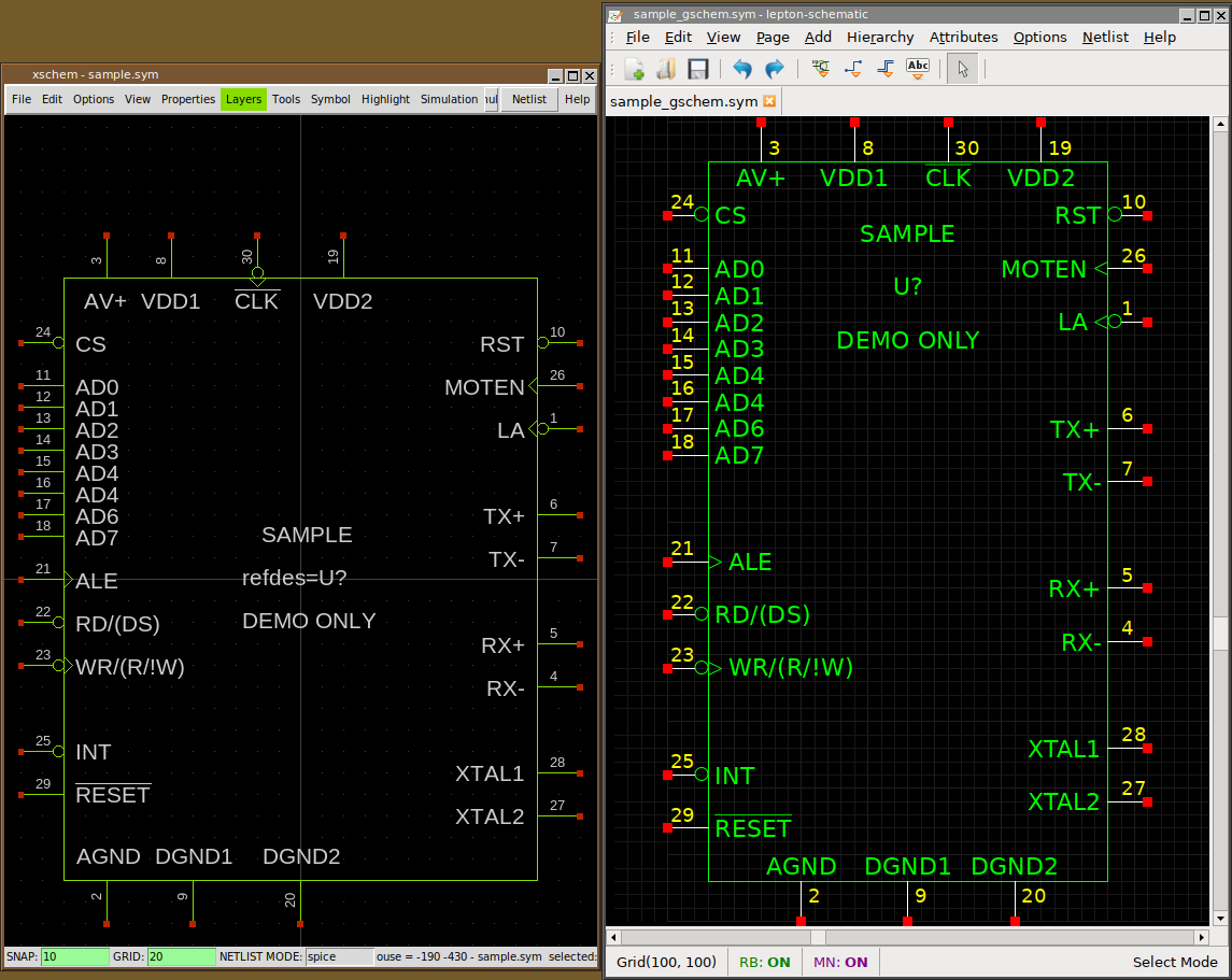
The resulting symbol is shown here under, side-compared with the same symbol generated by djboxsym for gschem:

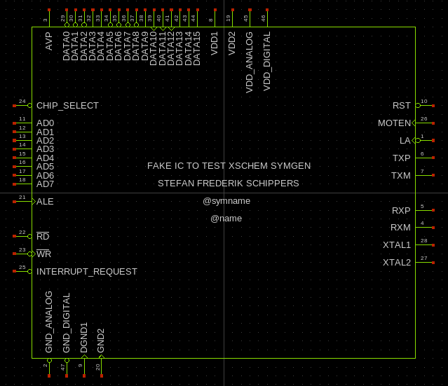
Another sample2.symdef file specifically created to generate a perfectly valid xschem symbol (including attributes for spice netlisting) is the following:
#  <pinnumber>  <direction>[<circle><edge_trigger>] <name>
# circle: !
# edge_trigger: >
# direction is mandatory: i=input, o=output, b=bidirectional (inout)

[labels]
FAKE IC TO TEST XSCHEM SYMGEN
STEFAN FREDERIK SCHIPPERS
@symname
@name
! type=subcircuit
! format="@name @pinlist @symname"
! template="name=x1"
--vmode
[left]
24   i!   CHIP_SELECT
.bus
11   i    AD0
12   i    AD1
13   i    AD2
14   i    AD3
15   i    AD4
16   i    AD5
17   i    AD6
18   i    AD7

21   i>   ALE

22   i!   \_RD\_
23   i!>  \_WR\_
25   i!   INTERRUPT_REQUEST
[right]
10   i!   RST
26   i>   MOTEN
1    i!>  LA
6    o    TXP
7    o    TXM

5    i    RXP
4    i    RXM
28   i    XTAL1
27   i    XTAL2
[top]
3    io    AVP
.bus
29  o!    DATA0
30  o!    DATA1
31  o!    DATA2
32  o     DATA3
33  o     DATA4
34  o!    DATA5
35  o!    DATA6
36  o!    DATA7
37  o!    DATA8
38  o     DATA9
39  o>    DATA10
40  o>    DATA11
41  o>    DATA12
42  o     DATA13
43  o     DATA14
44  o     DATA15

8    io    VDD1
19   io    VDD2
45   io    VDD_ANALOG
46   io    VDD_DIGITAL
[bottom]
2    io!   GND_ANALOG
47   io!   GND_DIGITAL
9    io>   DGND1
20   io>   GND2

some extensions of xschem's symdef text file format with respect to original djboxsym format:
-
In addition to optional ! (inversion bubble) and > (edge trigger) specifiers
XSCHEM's symgen.awk accepts a pin direction specifier,
i, o, io and p (latter one for power pins, treated by xschem as inout)
for 'input', 'output', 'inout' (bidirectional) direction and 'power'. These attributes are fundamental
for digital simulations (Verilog, Vhdl). If this specifier is missing (as it is in djboxsym
.symdef files) then the direction is assumed as b (inout).
XSCHEM does not have any specific direction for power pins so they are treated as 'inout'
Port direction specifiers are indeed supported also by 'djboxsym' but not documented. - Option --vmode given before any pin declaration like in djboxsym sets vertical orientation for top / bottom pins.
- .bus specifier can be used for all pin orientations, left, top, right, bottom if --vmode is enabled, otherwise it will affect only spacing of left/right pins.
- Option --auto_pinnumber given before any pin declaration lets symgen.awk automatically add pin numbers, so the first field may be omitted
- Edge trigger (>) and inversion bubble (!) specifiers are drawn on all sides, not only left/right.
- Option --hide_pinnumber given before any pin declaration avoids pin numbers in generated symbol. If this option is used it is mostly done together with --auto_pinnumber to get rid of pin numbers completely.