SYMBOL PROPERTY SYNTAX
GENERAL RULES
For symbols a global property string (to show it press 'q' when nothing is selected and Options->Symbol global attrs is selected) defines at least 3 attributes:
- type defines the the type of symbol. Normally the type attribute describes the symbol and is ignored by XSCHEM, but there are some special types:
- subcircuit: the symbol has an underlying schematic representation, when producing the netlist XSCHEM has to descend into the corresponding schematic. This will be covered in the subcircuits chapter.
- primitive: the symbol has a schematic representation, you can descend into it but the netlister will not use it. This is very useful if you want to netlist a symbol using only the format (or vhdl_format or verilog_format depending on the netlist type) attribute or use the underlying schematic. By setting the attribute back to subcircuit and deleting (or setting to false) the verilog_format of vhdl_format attribute you can quickly change the behavior. For spice netlists the format attribute is always used also for subcircuits instantiation so always leave it there.
- Any value different from subcircuit or primitive will cause xschem to not use any schematic file even if it exists. Xschem will not allow to descend into an existing schematic.
- label: the symbol is used to label a net. These type of symbols must have one and only one pin, and the template string must define a lab attribute that is passed at component instantiation to name the net it is attached to.
- probe: this denotes a probe symbol that may be backannotated with a backannotation script (example: ngspice_backannotate.tcl).
- ngprobe: This is a probe element that uses a 'pull' method to fetch simulation data and display it in current schematic. The data displayed is thus dynamic, multiple instances of the same symbol with annotators will display operating point data for that particular instance without the need to update the backannotation as is required for annotators using the 'push' annotation method.
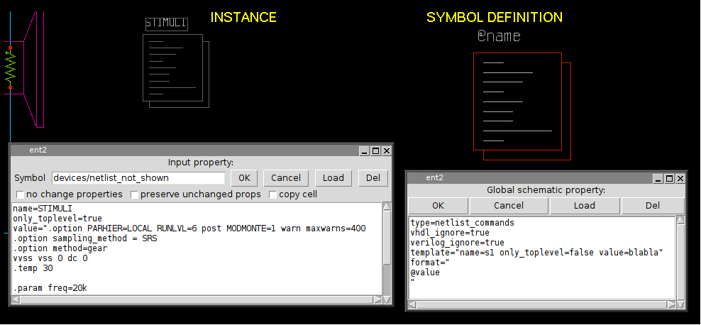
- netlist_commands: the symbol is used to place SPICE commands into a spice netlist. It should also have a value attribute that may contain arbitrary text that is copied verbatim into the netlist. More on this in the netlist slide.
- format: The format attribute defines the syntax for the SPICE netlist. the @
character is a 'substitution character', it means that the token that follows is a parameter
that will be substituted with the value passed at component instantiation. If no
value is given there a value will be picked from the attribute declared in the template
string.
The @pinlist is a special token that will be substituted with the name of the wires that connect to symbol pins, in the order they are created in the symbol. See the pin ordering section in the xschem properties slide. if the order of pins for a NMOS symbol is for example, d,g,s,b, then @pinlist will be expanded when producing a netlist to the list of nets that connect to the symbol drain, gate, source, body respectively. There is also a special way to define single pins: @@d for example will be replaced by XSCHEM with the net that connects to the d pin of the symbol. so for example @pinlist is equivalent to @@d @@g @@s @@b. However using @pinlist and setting the correct pin ordering in the symbol pins will make netlist generation faster. This is important for very big components with lot of pins, and @pinlist is the default when symbol is generated automatically (Symbol ->Make symbol menu of <Shift>A key).
The format attribute may contain a @spiceprefix string immediately preceding (with no spaces) the @name attribute.. This will be substituted with value given in instance (example: spiceprefix=X) but *ONLY* if Simulation->Use 'spiceprefix' attribute is set. This allows to create different netlists for simulation (example: all MOS are defined as subcircuits) or LVS (no device subcircuits). - lvs_format: This is the netlisting format attribute that is automatically selected if Xschem is set to produce a LVS netlist (Simulation->LVS netlist: top level is a subckt). This means that a symbol may have two different attributes for netlisting: format use dfor spice simulations and lvs_format for schematic to layout (LVS) comparison. More in general the xschem command xschem set format my_format will instruct xschem to use my_format as netlisting rule for components that have this attribute defined. If symbols do not have the my_format attribute the default fallback (format for spice netlist) is used.
- template: Specifies default values for symbol parameters
- select: specify an attribute value (not the attribute name) to select when editing properties of a placed instance of the symbol. Specifying select=* will select all the attribute text.
Only symbols of type subcircuit or primitive may be descended into with the 'e' bindkey if they have a schematic view.
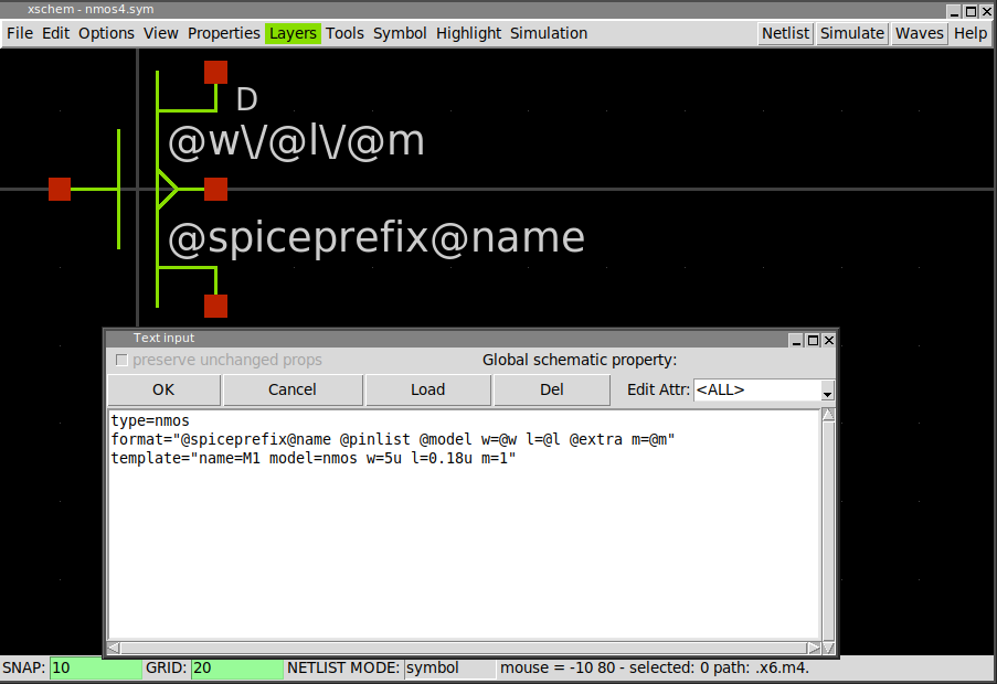
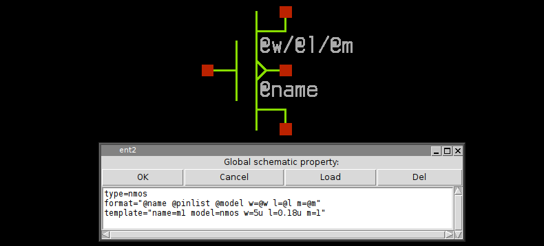
The order these attributes appear in the property string is not important, they can be on the same line or on different lines:
type=nmos format="@name @pinlist @model w=@w l=@l m=@m" template="name=m1 model=nmos w=5u l=0.18u m=1"
format="@name @pinlist @model w=@w l=@l m=@m"
template="name=m1 model=nmos w=5u l=0.18u m=1"
type=nmos
As you see double quotes are used when attribute values have spaces. For this reason if double quotes are needed in an attribute value they must be escaped with backslash \"
since the symbol global property string is formatted as a space separated list of attribute=value items, if a value has spaces in it it must be enclosed in double quotes, see for example the symbol template attribute: template="name=m1 model=nmos w=5u l=0.18u m=1" or the the format attribute: format="@name @pinlist @model w=@w l=@l m=@m". As a direct consequence a literal double quote in property strings must be escaped (\")
ATTRIBUTE SUBSTITUTION
XSCHEM uses a method for attribute substitution that is very similar to shell variable expansion
done with the $ character (for example
$HOME --> /home/user) The only
difference is that XSCHEM uses the '@' character. The choice of '@' vs '$' is simply because
in some simulation netlists shell variables are passed to the simulator for expansion, so to avoid the
need to escape the '$' in property strings a different and less used character was chosen.
A literal @ must be escaped to prevent it to be interpreted as the start of a token to be
substituted (\@). If a non space character (different than @) ends a token it must be escaped.
Attribute substitution with values defined in instance attributes takes place in symbol
format attribute and in every text, as shown in below picture.
In recent xschem versions a % prefixed attribute (example: %var) can be used
instead of a
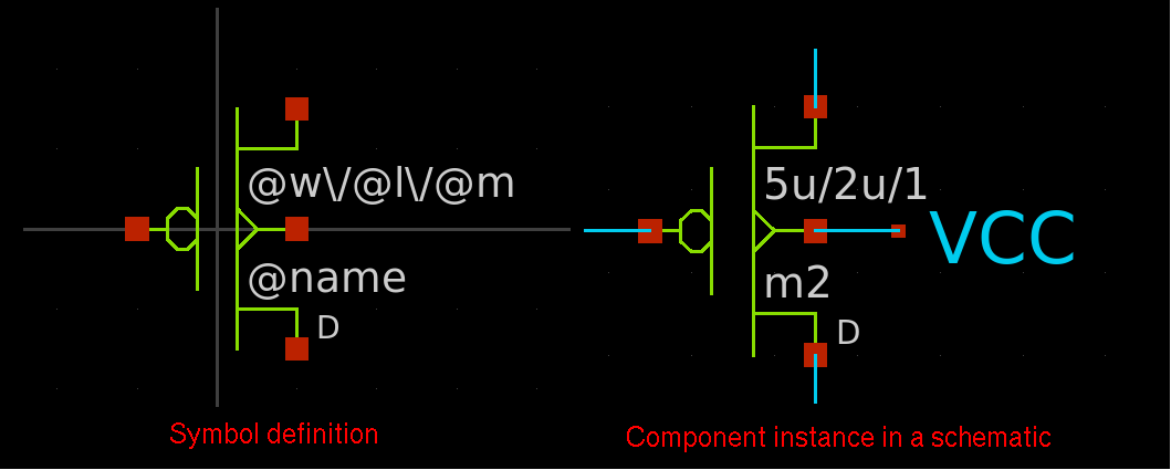
If no matching attribute is defined in instance (for example we have @W in symbol and no W=... in instance) the @W string is substituted with an empty string.
OTHER PREDEFINED SYMBOL ATTRIBUTES
- vhdl_ignore
- spice_ignore
- verilog_ignore
- tedax_ignore
- spectre_ignore
- lvs_ignore
- vhdl_stop
- spice_stop
- verilog_stop
- tedax_stop
- spectre_stop
- spice_primitive
- vhdl_primitive
- verilog_primitive
- spectre_primitive
- default_schematic
- spice_sym_def
- verilog_sym_def
- vhdl_sym_def
- spectre_sym_def
These 5 attributes tell XSCHEM to ignore completely all instances of the symbol in the respective netlist formats.
Allowed values for these attributes are true (or open), false and
short
If short is specified all symbol instances will short together all their pins. For this to work
only one of the nets connected to the symbol may have a net label attached to it. All other nets will take this name.
If more labeled nets connect to the shorted symbol a net short error is reported.
Shorted symbol instances are displayed in the pin color (red) layer. See some images in the
component properties man page when describing the same instance
based attributes.
Disabled symbols (spice_ignore=true or spice_ignore=open) are displayed in grey.
This attribute works in the same way as above attributes, may take the values true (or open), false or short, and will affect the symbol behaviour in the same way, but only if tcl variable lvs_ignore is set to 1. This can be done in the Simulation menu: Set 'lvs_ignore' variable. If this lvs_ignore is set on the symbol it will be shorted / ignored or kept as is depending on its lvs_ignore attribute and will be effective in all netlisting formats. This is mostly used to modify the produced netlist automatically when doing schematic vs layout (LVS) comparison.
These 4 attributes will avoid XSCHEM to descend into the schematic representation of the symbol (if there is one) when building the respective netlist format. For example, if an analog block has a schematic (.sch) file describing the circuit that is meaningless when doing a VHDL netlist, we can use a vhdl_stop=true attribute to avoid descending into the schematic. Only the global property of the schematic will be netlisted. This allows to insert some behavioral VHDL code in the global schematic property that describes the block in a way the VHDL simulator can understand.
Same as above _stop attributes, but in this case the schematic subcircuit is completely ignored, only the 'format' string is dumped to netlist. No component/entity is generated in vhdl netlist, no module declaration in verilog, no .subckt in spice, no schematic global attributes are exported to netlist.
If set to ignore xschem will not descend into the symbol associated schematic and will not complain if this schematic does not exists. To descend into a schematic instances must specify a schematic attribute, otherwise no descending and expansion occurs.
If any of these attributes are present and not empty and the symbol type is set to subcircuit
the corresponding netlister will ignore the schematic subcircuit
and dump into the netlist the content of this attribute. The typical usage is to include a file, example:
verilog_sym_def="tcleval(`include \"[abs_sym_path verilog_include_file.v]\")"
For spice netlists if @pinlist is used in format string and spice_sym_def attribute is defined the port order will be derived from the subcircuit referenced by the spice_sym_def attribute.
In this example a verilog_include_file.v is included using the verilog `include directive.
In order to generate a full path for it the abs_sym_path TCL function is used that searches for this file
in any of the XCHEM_LIBRARY_PATH directories. Since TCL is used the attribute is wrapped into a tcleval(...),
The following will appear in the generated netlist:
// expanding   symbol:  verilog_include.sym # of pins=3
// sym_path: /home/schippes/.xschem/xschem_library/verilog_include.sym
`include "/home/schippes/.xschem/xschem_library/verilog_include_file.v"
If set to true the symbol will be highlighted when one of the nets attached to its pins are highlighted.
If set to true the #n:net_name symbol attributes will display the net names attached to pin terminals. the n is a pin number or name.
This attribute is only useable in netlist_commands type symbols (netlist.sym, code.sym,...)
if set to end it tells XSCHEM that
the component instance of that symbol must be netlisted at the end, after all the other elements.
This is sometimes needed for SPICE commands that must given at the end of the netlist.
This will be explained more in detail in the netlisting slide.
The place=header attribute is only valid only for netlist_commands
type symbols and spice netlisting mode, it tells XSCHEM that this component must be
netlisted in the very first part of a spice netlist.
This is necessary for some spice commands that need to be placed before the rest of the netlist.
generic_type defines the type of parameters passed to VHDL/Verilog components. Consider the following MOS symbol definition; the model attribute is declared as string and it will be quoted in VHDL netlists.
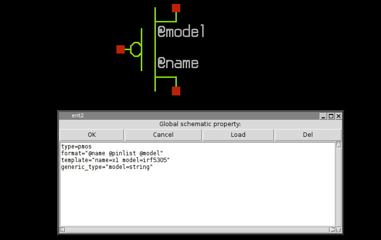
the resulting netlist is shown here, note that without the generic_type attribute the irf5305 string would not be quoted.
entity test2 is
end test2 ;

architecture arch_test2 of test2 is
signal d : std_logic ;
signal s : std_logic ;
signal g : std_logic ;
begin
x3 : pmos3
generic map (
   model => "irf5305"
)
port map (
   d => d ,
   g => g ,
   s => s
);

end arch_test2 ;
This property specifies that some parameters defined in the format string are to be considered as additional pins. This allows to realize inherited connections, a kind of hidden pins with connections passed as parameters. Example of a symbol definition for the following cmos gate:
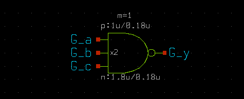
the symbol property list defines 2 extra pins , VCCPIN and VSSPIN that can be assigned to at component instantiation. The extra property tells XSCHEM that these 2 parameters are connection pins and not parameters and thus must not be declared as parameters in the .subckt line in a spice netlist:
type=subcircuit
vhdl_stop=true
format="@name @pinlist @VCCPIN @VSSPIN @symname wn=@wn ln=@ln wp=@wp lp=@lp m=@m"
template="name=x1 m=1
+ wn=30u ln=2.4u wp=20u lp=2.4u
+ VCCPIN=VCC VSSPIN=VSS"
extra="VCCPIN VSSPIN"
generic_type="m=integer wn=real ln=real wp=real lp=real VCCPIN=string VSSPIN=string"
verilog_stop=true
with these definitions the above schematic will be netlisted as:
**.subckt prova1
x2 G_y G_a G_b G_c VCC VSS lvnand3 wn=1.8u ln=0.18u wp=1u lp=0.18u m=1
**.ends
* expanding symbol: customlogicLib/lvnand3 # of pins=4
.subckt lvnand3 y a b c VCCPIN VSSPIN wn=30u ln=2.4u wp=20u lp=2.4u
*.opin y
*.ipin a
*.ipin b
*.ipin c
m1 net2 a VSSPIN VSSPIN nlv w=wn l=ln geomod=0 m=1
m2 y a VCCPIN VCCPIN plv w=wp l=lp geomod=0 m=1
dxm2 0 VCCPIN dnwell area='(wp + 57u)*(lp + 31u)' pj='2*(wp +57u)+2*(lp +31u)'
m3 y b VCCPIN VCCPIN plv w=wp l=lp geomod=0 m=1
dxm3 0 VCCPIN dnwell area='(wp + 57u)*(lp + 31u)' pj='2*(wp +57u)+2*(lp +31u)'
m6 y c net1 VSSPIN nlv w=wn l=ln geomod=0 m=1
m4 y c VCCPIN VCCPIN plv w=wp l=lp geomod=0 m=1
dxm4 0 VCCPIN dnwell area='(wp + 57u)*(lp + 31u)' pj='2*(wp +57u)+2*(lp +31u)'
m5 net1 b net2 VSSPIN nlv w=wn l=ln geomod=0 m=1
.ends
Without the extra property in the cmos gate symbol the following incorrect netlist will be produced:
**.subckt prova1
x2 G_y G_a G_b G_c VCC VSS lvnand3 wn=1.8u ln=0.18u wp=1u lp=0.18u m=1
**** begin user architecture code
**** end user architecture code
**.ends


* expanding symbol: customlogicLib/lvnand3 # of pins=4


.subckt lvnand3 y a b c wn=30u ln=2.4u wp=20u lp=2.4u VCCPIN=VCC VSSPIN=VSS
*.opin y
*.ipin a
*.ipin b
*.ipin c
m1 net2 a VSSPIN VSSPIN nlv w=wn l=ln geomod=0 m=1
m2 y a VCCPIN VCCPIN plv w=wp l=lp geomod=0 m=1
dxm2 0 VCCPIN dnwell area='(wp + 57u)*(lp + 31u)' pj='2*(wp +57u)+2*(lp +31u)'
m3 y b VCCPIN VCCPIN plv w=wp l=lp geomod=0 m=1
dxm3 0 VCCPIN dnwell area='(wp + 57u)*(lp + 31u)' pj='2*(wp +57u)+2*(lp +31u)'
m6 y c net1 VSSPIN nlv w=wn l=ln geomod=0 m=1
m4 y c VCCPIN VCCPIN plv w=wp l=lp geomod=0 m=1
dxm4 0 VCCPIN dnwell area='(wp + 57u)*(lp + 31u)' pj='2*(wp +57u)+2*(lp +31u)'
m5 net1 b net2 VSSPIN nlv w=wn l=ln geomod=0 m=1
**** begin user architecture code
**** end user architecture code
.ends
as you can see the VSSPIN and VCCPIN are listed as parameters in addition as pins in the netlist.
This attribute is similar to the extra attribute and is used for verilog netlist. Nodes listed in this attribute value will be used as additional pin connections.
the extra attribute is still used in verilog netlist as a list of attributes NOT to pass as symbol parameters
You may assign the following attributes to an instance: name=X1 VPWR=VCC VGND=GND subckt=NOR2_1 and you want to have VCC and GND connections to the symbol in the Verilog netlist but do not want any of these attributes to be passed as symbol parameters. In this case you set: verilog_extra="VPWR VGND" and extra="VPWR VGND subckt" since subckt is probably a spice attribute and you don't want it in verilog.
This attribute allows to define the pin directions of verilog_extra symbol ports.
If unspecified the default is
inout. Allowed values are input, output, inout.
Example: verilog_extra_dir="VPWR=input VGND=input"
If this attribute is defined in symbol it will be used as a prefix to the symbol name and subcircuit expansion in verilog netlists.
Defines the direction of a symbol pin. Allowed values are in, out, inout.

For packaged devices (tEDAx netlists) : indicate the position of the pin on the package.
This can be overriden at instance level by attributes pinnumber(name) set in the instance
for tEDAx netlists.
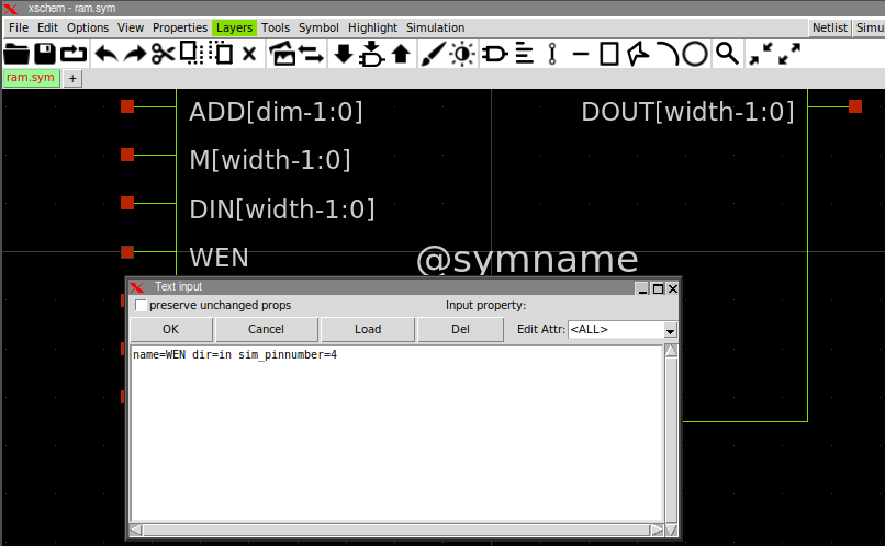
... Or you can assign these in the schematic pins, if you use the "Make symbol from schematic"
function ('a' key) these attributes will be transferred to the symbol.
The sim_pinnumber attributes that determine the netlist port ordering are those defined in the symbol.

For sorting to happen all symbol pins must have a sim_pinnumber attribute.
If some pins miss this attribute no sorting is done and pin ordering will be unchanged,
the stored order of symbol pins will be used (first created pin netlisted first).
If there are duplicate sim_pinnumber attributes (but all pins have this attribute) sorting
will happen but relative ordering or pins with identical sim_pinnumber is undefined.
As an example you may give sim_pinnumber=9999 on a symbol output and sim_pinnumber=1 on all other
pins if you only require the output pin to be netlisted at the end, and don't care about
the other pin ordering.
This attribute instructs xschem to do a 'propagate highlight' from the pin with this attribute to the pin n. The number 'n' refers to the pin sequence number (do a shift-S after selecting destination pin to know this information).
This attribute is used in the xschem embedded digital simulation engine: propagate logic simulation to the output pins n,[m,...]. The logic function is defined via the 'functionn' global attribute. There is one 'functionn' for each n output pin. see 'functionn' attribute for more info.

A clock attribute defined on input pins add some information on the pin function as follows:
- clock=0 This indicates an 'active low' clock signal for flip-flops
- clock=1 This indicates an 'active high' clock signal for flip-flops
- clock=2 This indicates an 'active low' reset signal for flip-flops
- clock=3 This indicates an 'active high' reset signal for flip-flops
This attribute is set in the symbol global attributes and specifies the logic function to be applied to the associated output pin. The format is: function<n>="...logic function..." where the number <n> refers to the sequence number of the output pin (do a 'Shift-S' after selecting the pin to know its sequence number). Multiple functions (function3="...", function4="...") can be defined in case of elements with multiple outputs.
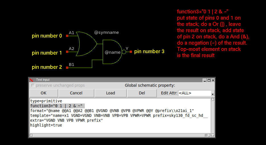
Commands that can appear in functions are:
- n: A digit indicates to put on the stack the logic value (0, 1, X) of pin with sequence number n The sequence number of a pin my be obtained by clicking the red square of the pin and pressing Shift-S.
- &: Does a logical AND operation of the last 2 elements on top of the stack, the result is left on the stack
- |: Does a logical OR operation of the last 2 elements on top of the stack, the result is left on the stack
- ^: Does a logical XOR operation of the last 2 elements on top of the stack, the result is left on the stack
- ~: Does a logical Negation operation of the last element on top of the stack, the result is left on the stack
- M: preceeded by 3 element 'a', 'b', 'm', return 'a' if 'm' == 0, 'b' if 'm'==1, else 'X'
- m: same as above, but don't update if 'm' not 1 or 0. Used to avoid deadlocks.
- z: preceeded by 2 elements, 'a', 'e', return 'a' if 'e' == 1 else Z (hi-Z)
- d: Duplicates top element on the stack
- x: Exchanges the 2 top elements on the stack
- r: Rotate down: bottom element of stack goes to top
- H: Puts a Logic '1' on the stack
- L: Puts a Logic '0' on the stack
- Z: Puts a Logic 'Z' on the stack
- U: Puts a Logic 'U' on the stack (do not assign to node)
The remaining value on the stack is the value that is returned and assigned to the output pin.
a global=true property in a label type symbol will declare the corresponding net as 'global'.
For spectre netlists a global=ground attribute will specify a ground node
(an alias for the '0' node) spiec netlister ignores the ground specification and will
just set the node as global.
In spectre netlist ground nodes are also global.
Global nets in spice netlists are like global variables in a C program, these nets are accessible at any
hierarchical level without the need of passing them through pin connections.

If any of these 4 properties if set to true the symbol will be netlisted in the specified format. This is only valid if the split file netlisting mode is active (Options -> Split netlist). This is very rarely used but is required in mixed mode simulations, where part of the system will be handled by an analog simulator (spice) and another part of the system by a digital Verilog / VHDL simulator.
This is the Verilog equivalent of the format property for Spice primitives. This is a valid definition for a 2 input inverted XOR gate:
verilog_format="xnor #(@risedel , @falldel ) @name ( @@Z , @@A , @@B );"
same as above for VHDL primitives.
same as above for tEDAx netlists.
This attribute contains a SPICE .model or .subckt specification (device_model=".model D1N4148 D ....") that will be printed at end of netlist only once for the specified component (D1N4148 in the example).
This attribute contains a SPECTRE model or subckt specification (spectre_device_model="model D1N4148 D ....") that will be printed at end of netlist only once for the specified component (D1N4148 in the example).
This attribute specifies an alternate schematic file to open when descending into the subcircuit:
schematic=inv_2.sch
It is possible to call a TCL procedure to decide the schematic to descend into:
schematic="tcleval([hierarchy_config @symname])"
The above schematic attribute will be evaluated by a hierarchy_config
TCL procedure (which must be defined) and the @symname attribute will be expanded to the name of the
symbol before passing the argument to the TCL procedure.
This allows user defined schematic selection in the hierarchy to simulate the design at different
details/abstraction levels.
One suggested approach is to define for a given opamp_65nm.sym symbol several schematics like
opamp_65nm.sch, opamp_65nm_pex.sch, opamp_65nm_aged.sch,
opamp_65nm_empty.sch, ... and define some user accessible method in hierarchy_config procedure
to select one of these 'switch' schematics.
This attribute can be attached to symbol elements, like lines, rectangles, polygons, arcs, texts, wires and instances (in case of lcc symbols). If set to true (symbol_ignore=true) the corresponding element will not be displayed when the symbol is instantiated.
The string inside the parenthesis will be evaluated if possible. Example:
expr(@W * @m )
Will be replaced by the product of @W * @m, if @W and @m can be resolved to numbers.
If not the expression will be left as is with the substituted parameters.
Suggestion: always put a space after a @param, otherwise xschem will not recognize
the correct param name.
PREDEFINED SYMBOL VALUES
- @name
- #pattern#@name
- @symname
- @model
This expands to the instance name of the symbol (like C1, R2, X3, ...) It is replaced with the value of the name=... attribute given when placing an instance of the symbol in a schematic.
This is a variation of the above where pattern is prefixed to all substituted @name
patterns. The difference with pattern@name is that in case of vector instances (this means
a placement of an instance with name=R2[3:0], for example) the pattern string
is added to all single instances when expanding the name. see below examples.
pattern@name where name=R2[2:0] is given in the instance placement,
expands to patternR2[2],R2[1],R2[0]
#pattern#@name where name=R2[2:0] is given in the instance placement,
expands to patternR2[2],patternR2[1],patternR2[0]
This expands to the name of the symbol
This expands to the name of the symbol, instead of taking the filename it will use the model
attribute as defined in the template symbol attribute. This is possible for spice and spectre netlists only.
Example:
     type=subcircuit
     format="@name @pinlist @model gain=@gain offset=@offset"
     template="name=X1 model=opamp gain=100 offset=0"
This expands to the symbol reference exactly as specified in the instance (the Symbol textbox if you edit the symbol attributes with q key).
This expands to the name of the symbol, keeping the extension (usually .sym)
This expands to the hierarchy path the symbol instance is placed in (example: xcontrol.xdec[3].xinv)
This expands to the list of nets that connect to symbol pins in the order they are set in the symbol
This expands to the net that connect to symbol pin named pin. This substitution
takes place only when producing a netlist (Spice, Verilog, Spectre, VHDL, tEDAx) so it is allowed to use this
value only in format,vhdl_format, tedax_format or verilog_format
attributes (see Netlisting slide)
The @#pin attribute is expanded to ?m net where m is the pin multiplicity and
net is the name of the net attached to the symbol pin. This information is needed
by the xschem netlister.
This expands to the net that connect to symbol pin at position n in the XSCHEM internal storage. This substitution
takes place only when producing a netlist (Spice, Verilog, Spectre, VHDL, tEDAx) so it is allowed to use this
value only in format,vhdl_format, tedax_format or verilog_format
attributes (see Netlisting slide)
This method of accessing a net that connects to a pin is much faster than previous one since XSCHEM does not need to
loop through symbol pin names looking for a match.
The @#n attribute is expanded to ?m net where m is the n-th pin multiplicity and
net is the name of the net attached to the symbol cwn-thpin pin. This information is needed
by the xschem netlister.
This expands to the value or property pin_attribute defined in the pin at position n
in the XSCHEM internal storage. This method of looking up properties is very fast.
Example: @#0:pinnumber: This expands to the value of the pinnumber defined in pin object at position 0 in the xschem
internal ordering. This format is very useful for slotted devices where the actual displayed pin number depends on the slot
information defined in the instance name (example: U1:2, slot number 2 of IC U1).
These tokens may be placed as text in the symbol graphic window, not in format strings.
This expands to the value or property pin_attribute defined in the pin named pin_name
This method of looking up properties is a bit slower since xschem has to do string matching to find out the pin.
Example: @#A:pinnumber: This expands to the value of the pinnumber defined in pin A.
This format is very useful for slotted devices where the actual displayed pin number depends on the slot
information defined in the instance name (example: U1:2, slot number 2 of IC U1).
These tokens may be placed as text in the symbol graphic window, not in format strings.
these expand to the net name attached to pin with name pin_name or with sequence number n.
these expand to the full hierarchy name of the net attached to pin with name pin_name or with sequence number n.
these expand to the voltage of the net attached to the pin with name pin_name or with sequence number n, extracted from simulation raw file (operating point or cursor b position)
This attribute will be replaced by the voltage of the net attached to the first pin (pin number 0) of the symbol
This attribute will be replaced by the current through the first pin of the primitive symbol according to the SPICE syntax. This can be used for elementary devices like voltage sources, resistors, mosfets, bjts and so on. For example @spice_get_current will display the drain current of a mosfet if this attribute is placed inside a MOS symbol.
This will specify in param the current to display, for example:
@spice_get_current_ibs to get the body-source current in a Mosfet,
@spice_get_current_ie to get the emitter current in a Bjt.
This will specify in param the voltage to display, for example:
@spice_get_modelvoltage_vth to get the Vth in a Mosfet
This will specify in param the model parameter to display, for example:
@spice_get_modelparam_gm to get the transconductance in a Mosfet
spice_node Will be replaced with the Spice simulated value for that node.
Examples:
Id=@spice_get_node i(\@m.@path@spiceprefix@name\.msky130_fd_pr__@model\[id])
will translate to:
Id=6.6177u
and:
Id=@spice_get_node i(\@m.@path@spiceprefix@name\.msky130_fd_pr__@model\[id]) A
will translate to:
Id=6.6177uA
note the required separator spaces around the spice node. Spaces are used here as
separators since spice nodes don't allow spaces.
escapes are used for 2 reasons:
mark a @ as a literal character instead of a the start of a @var token to be substituted
mark the end of a @var, like for example @var\iable. In this case @var will
be substituted by xschem instead of @variable.
Caveats: only one @spice_get_node is allowed in a string for now.
this indicates the last modification time of the .sch file of the symbol.
this indicates the last modification time of the .sym file of the symbol.
this indicates the last modification time of the schematic (.sch) containing the symbol instance.
this expands to the name of the schematic (.sch) containing the symbol instance.
this expands to the name of the schematic containing the symbol instance, without the extension (no .sch).
this expands to the name of the tol level schematic (.sch) containing the symbol instance.
this expands to the entire property string passed to the component.
this expands to the spice global property string of the schematic containing the symbol
this expands to the VHDL global property string of the schematic containing the symbol
this expands to the Verilog global property string of the schematic containing the symbol
this expands to the Spectre global property string of the schematic containing the symbol
TCL ATTRIBUTE SUBSTITUTION
Any attribute and symbol text can be embedded in a tcleval(....) construct, the string inside the
parentheses will be passed to the tcl interpreter for evaluation. This allows to use any tcl
variable/command/expression. Example:
spice_ignore="tcleval($::ignore_symbol)"
will cause the symbol to be ignored by the spice netlister if the ignore_symbol tcl variable is
existing and set to true